
Specialized Linkages
- Saleh Rzayev

- Jan 28, 2023
- 3 min read
In addition to changing the motions of objects or forces, more complex linkages have been designed to perform many specialized functions: These include drawing or tracing straight lines; moving objects or tools faster in a retraction stroke than in an extension stroke; and converting rotating motion into linear motion and vice versa. The simplest specialized linkages are four-bar linkages. These linkages have been versatile enough to be applied in many different applications. Four-bar linkages actually have only three moving links but they have one fixed link and four pin joints or pivots. A useful mechanism must have at least four links but closed-loop assemblies of three links are useful elements in structures. Because any linkage with at least one fixed link is a mechanism, both the parallel-motion and push-pull linkages mentioned earlier are technically machines.
Four-bar linkages share common properties: three rigid moving links with two of them hinged to fixed bases which form a frame. Link mechanisms are capable of producing rotating, oscillating, or reciprocating motion by the rotation of a crank. Linkages can be used to convert:
Continuous rotation into another form of continuous rotation, with a constant or variable angular velocity ratio
Continuous rotation into oscillation or continuous oscillation into rotation, with a constant or variable velocity ratio
One form of oscillation into another form of oscillation, or one form of reciprocation into another form of reciprocation, with a constant or variable velocity ratio
There are four different ways in which four-bar linkages can perform inversions or complete revolutions about fixed pivot points. One pivoting link is considered to be the input or driver member and the other is considered to be the output or driven member. The remaining moving link is commonly called a connecting link. The fixed link, hinged by pins or pivots at each end, is called the foundation link. Three inversions or linkage rotations of a four-bar chain are shown in Figs. 1, 2, and 3. They are made up of links AB, BC, CD, and AD. The forms of the three inversions are defined by the position of the shortest link with respect to the link selected as the foundation link. The ability of the driver or driven links to make complete rotations about their pivots determines their functions.
Drag-link mechanism, Fig. 1, demonstrates the first inversion. The shortest link AD between the two fixed pivots is the foundation link, and both driver link AB and driven link CD can make full revolutions.
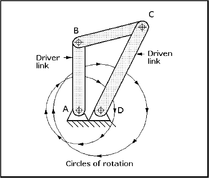
Fig 1: Four-bar drag-link mechanism: Both the driver link AB and driven link CD can rotate through 360°. Link AD is the foundation link.
Crank-rocker mechanism, Fig. 2, demonstrates the second inversion. The shortest link AB is adjacent to AD, the foundation link. Link AB can make a full 360 degree revolution while the opposite link CD can only oscillate and describe an arc.
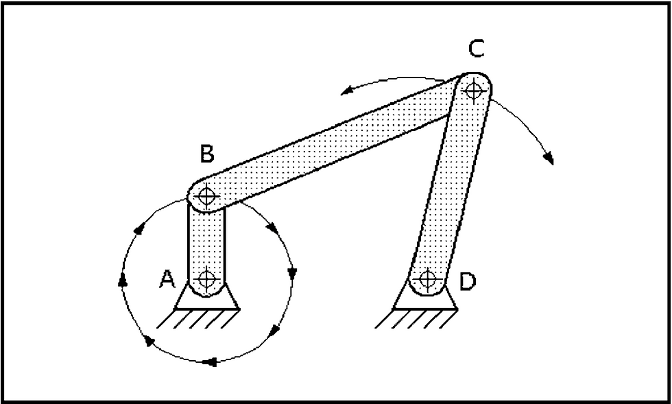
Fig 2: Crank-rocker mechanism: Link AB can make a 360° revolution while link CD oscillates with C describing an arc. Link AD is the foundation link.
Double-rocker mechanism, Fig. 3, demonstrates the third inversion. Link AD is the foundation link, and it is opposite the shortest link BC. Although link BC can make a full 360 degree revolution, both pivoting links AB and CD can only oscillate and describe arcs.
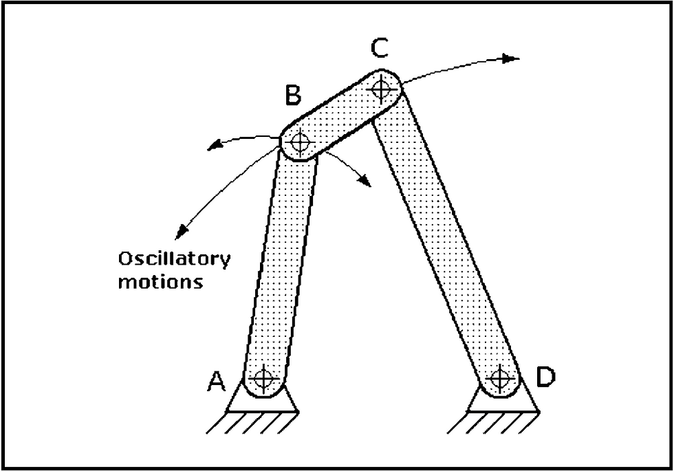
Fig 3: Double-rocker mechanism: Short link BC can make a 360° revolution, but pivoting links AB and CD can only oscillate, describing arcs.
The fourth inversion is another crank-rocker mechanism that behaves in a manner similar to the mechanism shown in Fig. 2, but the longest link, CD, is the foundation link. Because of this similarity between these two mechanisms, the fourth inversion is not illustrated here. A drag-link mechanism can produce either a nonuniform output from a uniform input rotation rate or a uniform output from a nonuniform input rotation rate.


Comments